Contactor Control
In a Battery Management System (BMS), contactor control serves a critical function. If the contactor fails to operate correctly, it cannot interrupt the current during abnormal conditions, thereby failing to prevent battery overcharging and overdischarging. The BMS needs the capability to detect contactor failures, including failure to open and failure to close. Contactor welding, which prevents disconnection, poses a potential threat.
Each contactor has its rated maximum lifespan, which denotes the maximum number of cycles it can endure under various switching conditions.
Soft Start and Pre-Charge Circuit
In multi-branch energy storage systems, the BCMU requires circuits with soft start or pre-charge functions to mitigate large circulating currents caused by significant voltage differentials between different clusters paralleled on the same bus. Such circulating currents can cause significant damage to contactors.
Typically, contactors should close under a smaller voltage differential, and current should only flow after the contacts are fully closed. The most common solution to address such issues is to use a soft start circuit (see Figure 8). This circuit utilizes a resistor and an additional contactor connected in series, which is then paralleled with a main contactor.
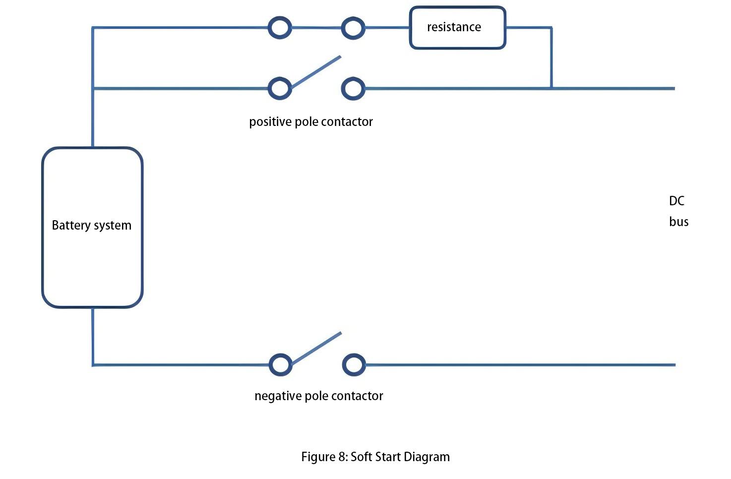
When the battery system is ready to connect to the DC bus, the branch contactors close to limit the current within a reasonable range through the resistor in the pre-charge circuit. As the battery system voltage gradually rises and the voltage difference with the DC bus becomes sufficient, closing the main contactor effectively short-circuits the pre-charge circuit, after which the contactor of the pre-charge circuit is reopened.
To enhance system reliability, BMS uses multiple contactors. If one contactor becomes welded, the second contactor can provide an effective isolation method.
Detection of Contactor Faults
Contactor fault detection generally employs two methods. One method involves measuring the actual high-voltage system to determine whether there is a conductive path between the two sides of the contactor. The other method is to install auxiliary contacts. Typically, the strategy with auxiliary contacts requires additional inputs and wiring, leading to more fault modes associated with improper operation of the auxiliary contacts. The high-voltage measurement method can directly detect the current status of the contactor circuit and has higher fault tolerance capabilities.
Determining contactor faults involves making a logical assessment based on the open/close status returned by the contactor and the current/voltage measurements within the battery cluster.
Thermal Management System
No matter whether it is the available capacity of the battery, the degree of degradation of the cells during cycling, or the temperature during the operation of the cells, energy storage systems will be equipped with cooling methods such as air cooling, liquid cooling, and immersion cooling. However, regardless of the cooling method used, the goals are twofold.
On one hand, minimizing the temperature difference within the same cluster of cells is preferable (series arrangement), aiming to achieve uniform cell degradation within the cluster. On the other hand, maintaining an average temperature of around 25 degrees Celsius for the entire cluster of cells with minimal deviation is ideal, approximating the operating environment of the cells to laboratory testing conditions. Additionally, the thermal management system must consider its power consumption, as all power consumed contributes to the self-use power of the energy storage system; excessive power consumption can adversely affect the efficiency of the entire energy storage system.
Electromagnetic Compatibility
In a large-scale energy storage system, there exists a highly complex electromagnetic environment, with one significant source of interference being the carrier waves from multiple parallel operating PCS systems. Asynchronous carrier waves can cause high-frequency interference that feedbacks through DC-side grounding capacitors to the battery side. The peak-to-peak value of this interference can reach thousands of volts.
Maintaining precise voltage and temperature measurements of battery cells for the BMS in such a strong electromagnetic interference environment poses a challenge. Ideally, the low-voltage and high-voltage systems operate independently without interference. However, in practical operation, low currents can still pass through isolation devices. This necessitates rigorous EMC testing for the BMS.
Insulation detection
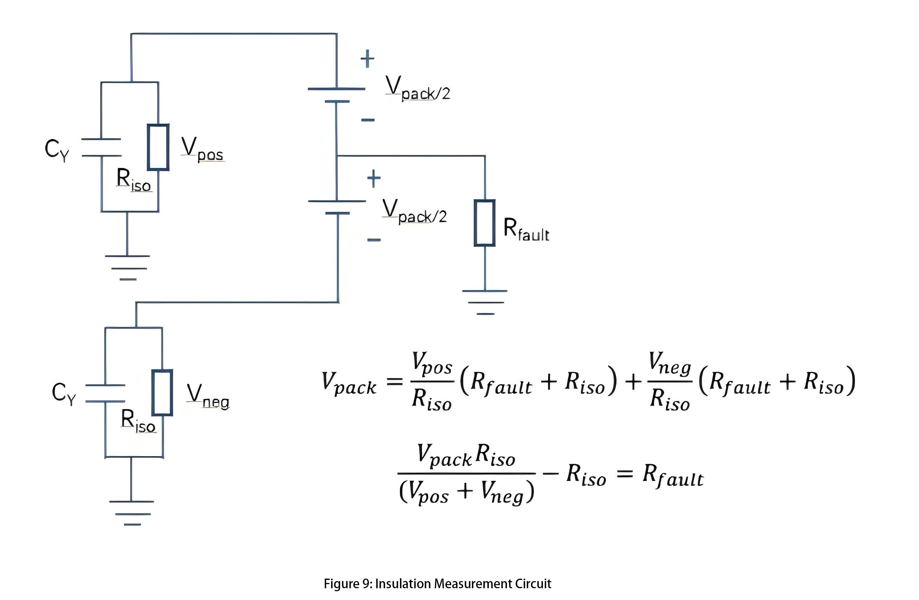
In energy storage systems, there are parasitic capacitances and conductances between insulation high-voltage components like battery modules and ground/chassis. These parasitic components require special consideration. Therefore, insulation detection circuits, either offline or online, should be integrated into the battery management system. Figure 9 provides a simple illustration of an insulation detection circuit.
The Rfault value can be calculated from two measurements. For each measurement, the known resistance Riso is plugged in between the ground and the positive and negative stages of the battery, and the voltage across the resistance is measured. When the measuring resistance Riso is connected, it and the Y-capacitor form an RC circuit. The capacitor must be filled before the measurement can be made. This determines the minimum time required to make this measurement.
BMS Software Component
Battery Model
In battery management systems, the purpose of battery modeling is to create a representation that uses easily measurable physical quantities (such as voltage, temperature, and current) to calculate physical quantities that cannot be directly measured (such as State of Charge - SOC and State of Health - SOH).
For lithium-ion batteries, there exists a one-to-one relationship between the open circuit voltage (Voc) of lithium ions and SOC, which can be represented by the SOC-OCV curve. This curve enables the real-time calculation of the battery's open circuit voltage (Voc) through the battery model, thereby allowing measurement of the real-time SOC of the battery.
Parameter Identification
In adaptive model parameterization, model parameters are determined based on the relationship between current and voltage. This involves continuously adjusting the model parameters so that the model output of current and voltage matches the actual measured current/voltage curve. The most typical algorithm used for parameter identification is recursive least squares.
By observing a series of data points from battery testing, actual measured current values are input into the model. Through model calculations, voltage values can be obtained. The error between the model-predicted voltage and the actually measured voltage is a crucial criterion for assessing the quality of the model.
The objective is to find a set of model parameters that minimize this error. Therefore, this error function serves as the objective function. Each iteration involves taking the derivative of the objective function with respect to each parameter and continuously updating the model parameter values until the desired effect is achieved.
For battery cells, parameter identification methods can be used to determine the operational status by evaluating whether the internal impedance values are within reasonable ranges. Classifying battery cell health into categories such as healthy, sub-healthy, fault warning, and fault states based on these parameter levels allows for timely replacement of cells nearing failure, thereby preventing major accidents.
Determining the safe operating region of energy storage systems
Based on the operational characteristics of the battery cells, the Battery Management System (BMS) needs to delineate the safe operating region for the energy storage system. If this region is overly conservative, the performance of the energy storage system may not be fully utilized, affecting its economic viability. Conversely, if the region is too aggressive, it could accelerate degradation of the energy storage system and even threaten its safe operation. Several key pieces of information are used to define the safe operating region of the entire energy storage system:
1. Individual Cell Voltage Range: What are the maximum and minimum voltage values within which individual cells can operate?
2. Individual Cell Temperature: What is the upper limit for normal operation temperature? What is the critical temperature at which thermal runaway and other destructive effects begin to occur? Given the specific thermal management system, what is the maximum charge/discharge current to maintain cell temperatures within a reasonable range?
3. Maximum Charge/Discharge Current: What is the maximum charge/discharge rate of the battery? Under constant power operation, what are the maximum charge/discharge current values and terminal voltage that can determine the maximum achievable charge/discharge power output of the energy storage system?
4. Critical Voltage Change Rate during Standard Charge/Discharge: What is the voltage change rate that reflects State of Health (SOH) and other fault information during standard charging and discharging?
5. Critical Temperature Change Rate during Standard Charge/Discharge: What is the temperature change rate during standard charging and discharging?
6. State of Charge (SOC): What is the Depth of Discharge (DoD) of the cells? What is the balancing strategy?
Since the energy storage system comprises numerous cells connected in series and parallel, it exhibits the "weakest link" effect. This means the performance of the entire battery pack is limit
Battery State of Charge (SOC) calculation
SOC (State of Charge) mainly refers to the ratio of the current charge (in Coulombs) available in a battery to its total charge capacity when fully charged. It is important to note that SOC and State of Energy (SOE) are distinct concepts, with SOE representing the area under the charge-discharge curve.
When calculating SOC, the following aspects need to be considered:
1. Coulomb efficiency: The Coulomb efficiency of lithium-ion batteries is typically around 99%. Therefore, formulas for charge and discharge incorporate the Coulomb efficiency factor.
2. Variation in battery terminal voltage: During actual charge and discharge processes, a battery's terminal voltage does not behave like an ideal voltage source; it fluctuates continuously. Thus, the State of Energy (SOE) is inconsistent at the same time interval.
3. Capacity variation with temperature: Battery capacity exhibits a nonlinear relationship with temperature.
4. Capacity variation with charge and discharge rates: At higher discharge rates, a battery's capacity decreases.
Remaining Capacity State of Health (SOH) calculation
The capacity of a cell will degrade over time with the number of charge/discharge cycles and total operating time. The State of Health (SOH) of a battery is primarily related to its effective capacity, impedance, and self-discharge rate. For calculating SOH, an approximate function can be established to model capacity degradation.
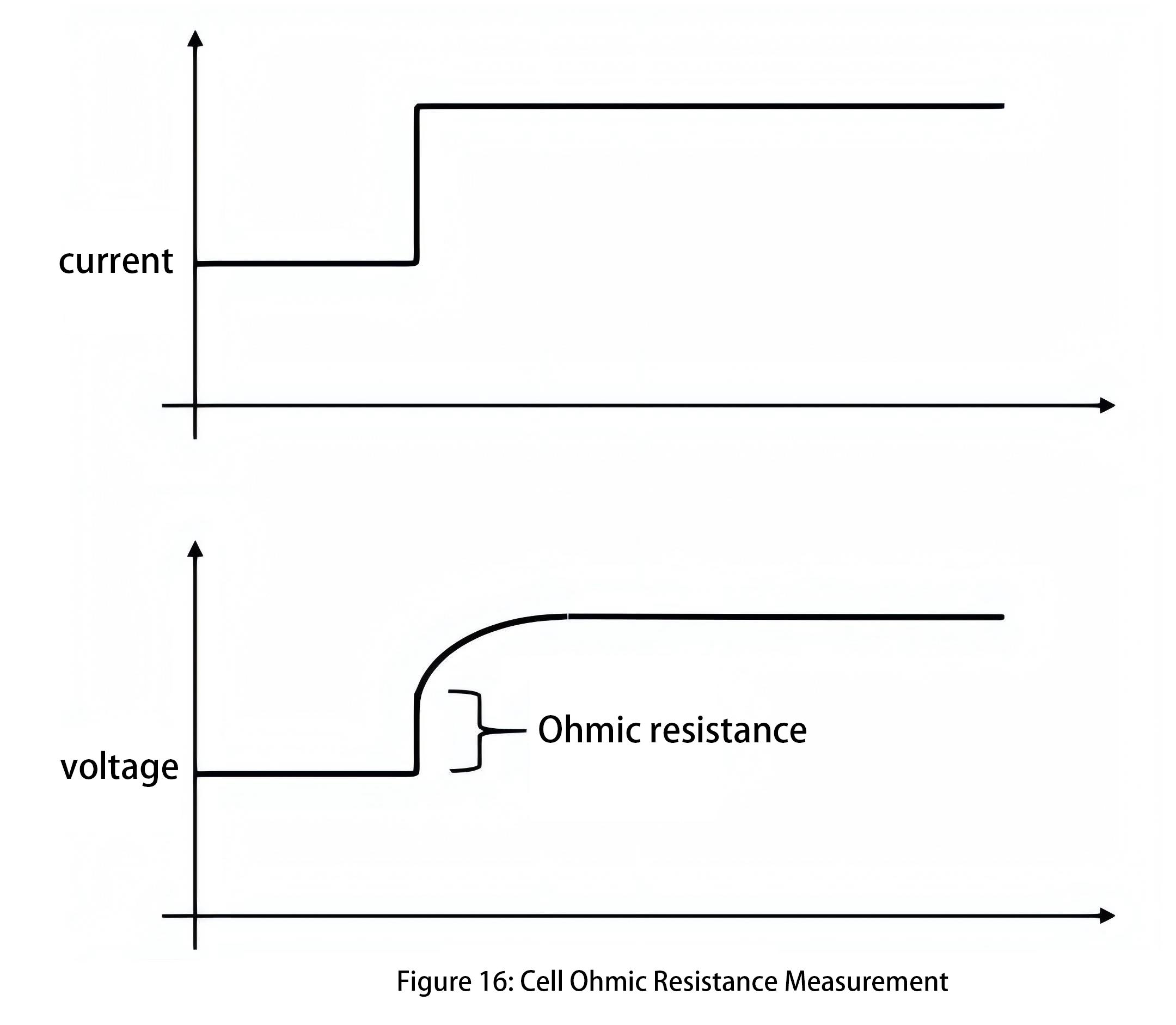
Furthermore, SOH is related to internal impedance values, which can be estimated by testing internal impedance to approximate SOH. Linear least squares fitting can be employed to fit a series of ordered pairs of voltage and current, providing a relatively accurate estimate of DC Ohmic resistance. The slope of the regression line obtained by least squares regression equals the impedance, while the intercept of the regression line represents the non-IR voltage value. Additionally, approximate values of step changes in current can detect corresponding transient voltage changes. The ratio of DeltaV/DeltaI can be used to calculate the Ohmic resistance at that point, as shown in Figure 16.
For large-scale energy storage systems, they typically operate through full charge and full discharge cycles, which effectively estimate the available capacity of the cells. However, the available capacity of cells is temperature-dependent. Therefore, when assessing capacity changes, it's preferable to conduct full charge and full discharge cycles at consistent temperatures or use temperature calibration factors to adjust capacity values.
Operating Mode
The BMS system employs one or more finite state machine algorithms responsible for controlling the battery's operational states. These state machines respond to external commands and monitor various internal conditions of the battery system. Typically, the battery system operates in "low power" or "sleep" mode. In this mode, the system minimizes power consumption from the high-voltage battery pack control to reduce cell inconsistency.
Even when the battery system is not actively running, it is essential to periodically wake the BMS from sleep mode. This is necessary for more accurate estimation of state of charge (SOC) and for appropriate cell balancing. Additionally, it allows for detection of various battery defects, including self-discharge.
Summary
Battery Management Systems (BMS) for large-scale energy storage systems are highly complex systems that need to consider various failure conditions of the energy storage system and respond with appropriate protective actions, ensuring the system operates within a reasonable and safe range.
The design of a Battery Management System can be divided into hardware and software components. The hardware components include embedded acquisition circuits, main control circuits, balancing circuits, as well as electrical devices such as circuit breakers and contactors. Among these, the precision of cell voltage and temperature acquisition is crucial, as it provides the fundamental data for the software and forms the basis for protective actions.
The software part includes calculations of cell State of Charge (SOC) and State of Health (SOH), and intelligent analysis of cell status. SOC and SOH values provide the basis for cell balancing, and the accuracy of SOC/SOH calculations affects the balancing efficiency of the energy storage system.
The effectiveness of cell balancing in an energy storage system determines how closely its cycle life approaches that of the individual cells. Therefore, the hardware and software of the BMS are complementary components of a systematic engineering approach, requiring in-depth analysis of cell operating characteristics. Starting from top-level design, every detail must be carefully considered to achieve an efficient and reliable battery management system.